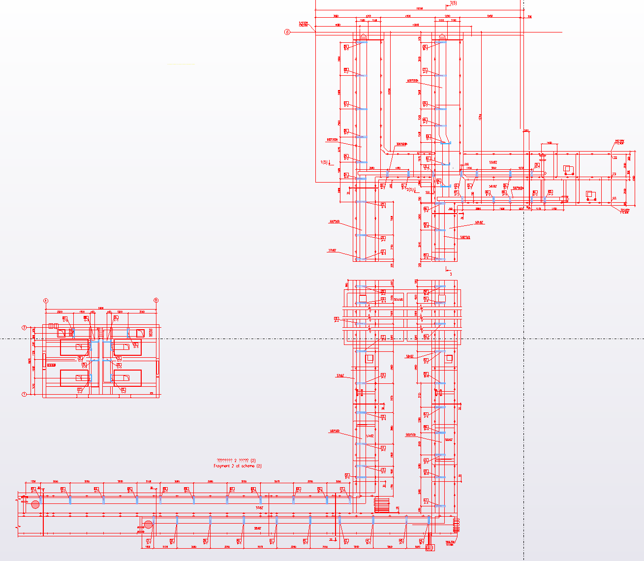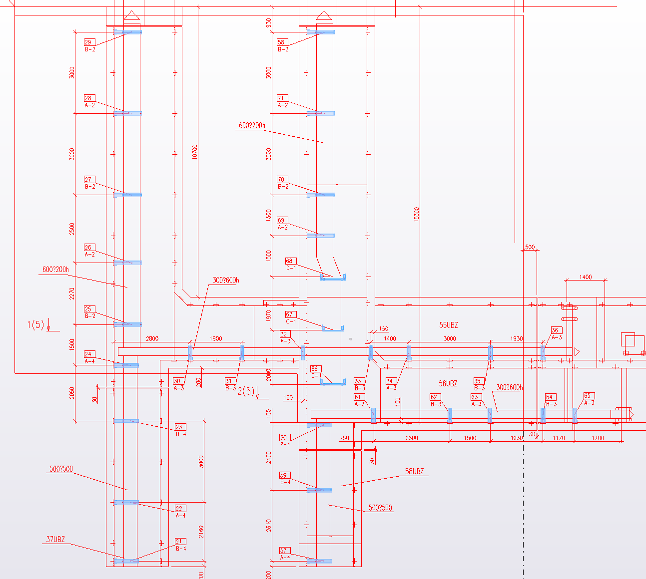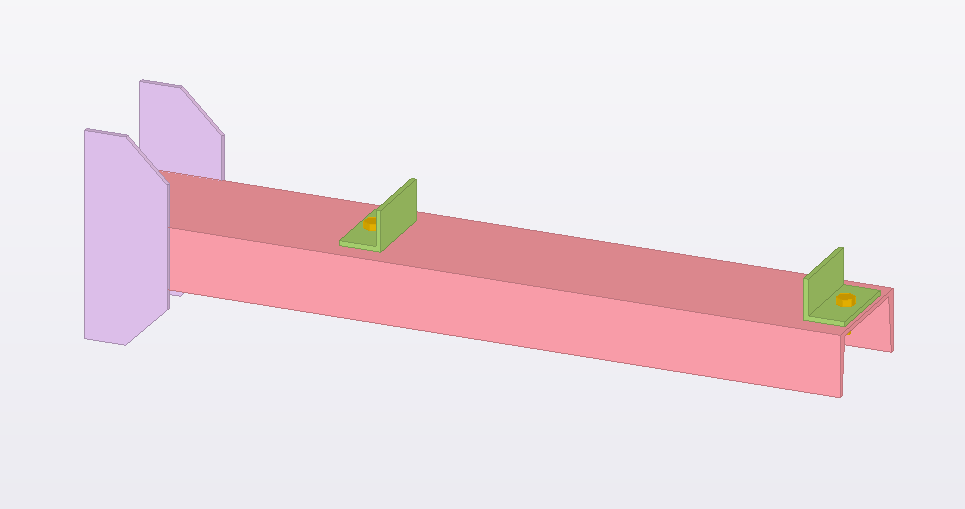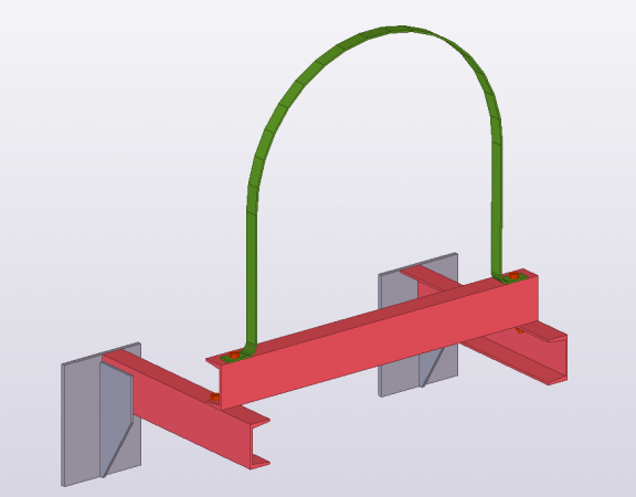


Before the construction of the building, you need a large amount of preliminary work, among other things - to create a plan for future construction with all drawings and details. We are talking about designing the CM and CMD.
KM – metal structures
The first stage of the Drawings. Development of metal structures begins at the moment, both obtained from the client source documents. A job is created by the developer, enlisting the cooperation necessary specialists. Face, that is to collect all the required information, It is responsible for the correctness of this information. These figures encompass all the required specification, image of the main projections, and to the same scheme of dislocation of elements and structural joints.
QMD – design metal exploded
It is on the basis of the Cabinet is formed, said drawings mark.
working blueprints QMD – this is unified specification for the creation and subsequent assembly and installation of designs. Set concludes at himself material for markup, obrabatyvaniya, welding, process, used to, to ensure a certain level of quality, as well as for structures installation.

what Unlike DRAWINGS CM of KMD?
The main discrepancy, what metalwork drawings KM are in the first stages of development, but KMD development - a follow-up, the final phase.
The first phase - the creation of common metal plans, its main components. And on the second worked already more detail:circuit details, steel grade, which will be used etc..
But it should be noted, that recently engineers emphasize a very small difference among these species DRAWINGS.
Indestructible one factor: KM - is the basis for design drawings KMD.
Often, it does lead to a certain blurring of faces, insofar as, the better foundation created, the easier it is to create it give specific, clarification. However, differences exist. The difference between these structures to the same design and the accompanying documents.
Rules of registration of drawings and CM CMD brand by section
Documents issued in accordance with the Russian Federation, the existing regulations. The volume of documents have to be acceptable, since unnecessary increase only spend time professionals, and insufficient volume will lead to a decrease in the quality of all subsequent works on the construction.
formlenie DRAWINGS
Making the graphic part of the documentation (design and working), it should be clearly guided by the relevant national standards.
This section should be considered:
- Format.
The greater the drawings, the more comfortable to carry them out, However, large drawings require special printing devices, Time to fold, especially when the designer is doing it yourself. Consequently, acceptable to choose A3 and A2 format. To perform the master plans are required, usually, A0, A1, A2.
- lines.
When placing DRAWINGS required to apply lines embodiments, defined by state standards. The right to use their show planner and competence will enable the drawing to be a good user experience.
When the images are created on the same scale, respectively, the thickness of all the lines is required to be uniform.
- scale drawings.
Selection of the scale is carried out with respect to image complexity. Use the smallest possible embodiment, which will ensure the clarity of the drawings and possible with them copies.
- SPDS.
A set of methodological documentation, which establishes the general technical requirements, priority for razrabatyvanie, accounting, preservation and application of the design documentation.
- ESKD.
A set of standards, describes a system of interrelated requirements for registration, development and use of engineering documentation.
- fonts (according to the National Standards 2.304-68).
- Hatching.
To depict the material, from which produce structure or its element, using conventional graphic symbol.
Material to draw a fine line graphic designation. Interval hatch within the boundaries of a single drawing always more interval at hatching, which is a metal.
- axes.
- The dimensions in the drawings.
- slopes, inscriptions.
- incisions, section, kinds, sites.
Paragraphs 8 by 11 applied according to GOST 21.1101-2013.
- Symbols (Symbols sanitation devices made in accordance with GOST 2.786-70).
- floor plan drawing.
- Drawing of the building section (according to GOST 21.1101-2013).
- The drawing of the facade of the building.

STAMPS
Stamps are issued in accordance with current building regulations. This section contains the main drawing dies, their description and files already created drafted stamps.
STATEMENTS AND SPECIFICATIONS
- Signature of the chief engineer of the project.
- List of working drawings.
- The list of specifications.
- List of the main sets of working drawings.
- List of used documentation.
- Specification fill openings of windows.
- List-departure stamps KMD.
- Document, determining the composition of the steel KMD.
- Data on building, are presented in table form (Floor number; number of rooms; their purpose, on the height and area information; other).
- List of interior decoration.
- list of flooring.
- List of construction fasteners.
PROJECT DOCUMENTATION
WORKING DOCUMENT
Typically, design of steel takes place in 3 phase.
- At this stage the technical possibility to use for the future structure of different of types of constructions, that, interacting statically, withstand the load and provide strength, commensurate options planning decisions, different location of the main load-bearing structures, various types of steel, profiles, else. This stage is called the technical or the variant design.
- The second phase has a design mark CM (metal structures).
- it KMD development DRAWINGS. They should be so detailed and kept procedure for the development of drawings KMD designers, that in the workshops of the factory worker with no problems able to produce part of the future buildings, and component assembly installation wizard and facilities, applying the drawings, I was able to do his job. In most cases, workers blueprints are being created on factories at own design department for use in the workshops of this industrial enterprise, however, such work may be on the order. In this scenario, the organization, which will design drawings, It is obliged to take account of technology and equipment, present at the factory.
After the construction drawings are stored in the SMS enterprises and passport data are buildings or structures.
The composition of the project and working documents
documentation Package (Design and working) KM for creating a one or two step.
Everything is subject to the complexity of the structure of the future, and describes the contract and the RFP.
Project documentation consists of 2 parts: textual and graphical.
The first part includes data on approved technical and engineering solutions, the results of the calculation, argumentation solutions, references to normative documents.
The second comprises approved solutions in the form of drawings and diagrams.
Working documents, which is transmitted to the customer, consists of working drawings KM.
Composition section KM
According to the results of the collected materials to create a project KM, comprising:
- general information, described:
- Information about the load and impact, to calculate design;
- Information about a particular object;
- design designs diagram with information about the load and the impact with the required explanations (If you want to);
- sources of information on the existing rules for the design, terms of reference and documents, establishing standards and guidelines for rolled metal, as well as about the welds and fasteners;
- Description reciprocal adjacencies structural elements, performed during mounting;
- information about protecting structures from rust;
- requirements for the production and assembly;
- Symbols used and designations anchorages;
- other auxiliary data.
- Specification metal – list by varieties profiles, which is contains GUEST, brand steel and number profile by categories designs and on all future an object at whole.
- Registry data about section elements at addictions from acting at them efforts or constructive features.
- Scheme designs – are being created So, in order to position each element It was definitely definitely from considering geometry designed building. On schemes applied marking elements and typical knots, but also carried out their binding to already existing constructions, if a those are available.
- Nodes - all major components have to be exhaustively, thoroughly developed, do not forget to specify sectional node elements, their bindings, the number of bolts, etc..
Composition section KMD
- Title page. This section contains information about the client, designer and project name. On a sheet of stamps and signatures are put Attorneys persons. Since there are no clear rules of registration of title pages, their shape varies.
- Drawings of each component for all metal structures.
- Mounting-departure circuit elements labeled (parts, transported to the construction site).
- Data about the mounting compound.
- The drawings and diagrams fasteners, such as a bolt, rivet, other.
- Data about the mounting components and joints, types of connecting parts.
How is the cost of developing?
Price projection is due to a certain number of parameters, Consequently, is formed for each project separately. The cost depends on the following circumstances:
- co-weight steel structures, defined in Section KM;
- scope of the project;
- Date of completion;
- complexity of the project level;
- the availability of high-quality original documents;
- specific request of the customer, taken into account when designing.
What matters drawings KM development costs and CMD?
- The cost depends on the tonnage, ie. the cost of developing drawings KMD per ton metal structures. Current setting is convenient and customers, and developers.
- Price per hour engineer, spent on the project.
This option has gained popularity for foreign customers due to the fact, that he is familiar and comfortable for them.
- Unchanged documented cost of the whole project.
This calculation in comfort and style with a large number of similar projects or for small size design.
undoubtedly, each project is evaluated individually, but there are basic starting points for the facial features of different designs. The lower boundary of the price - a project with a large amount of design, top - small projects.
Drawings of metal structures: production time
The timeframe for drawing creation is fully subject to individual design, regular repetition of elements, uniformity components, Customer response to operational changes in coordination and oversights, deviations in the package of documents. Among other things, should take into account existing currently busy designers. Accurate and deadline for completion of work on the drawings KMD can be determined after a preliminary study of the drawings KM, which are provided by the client.
If you want to, the drawings may give and parts, what, First of all, will produce work, and secondly, the forced downtime reduced. Besides stipulated time interval issuing the first part and the amount of KMD further DRAWINGS.

Technology development KMD
- Any project created in the three-dimensional graphics, which will carefully consider every detail and dock project.
- Automatically generated by the program and specifications sheet.
- Information for machine tools with CNC in formats dxf and nc.
- Automatic numbering of all parts and assemblies.
Form the date set KMD
- PDF - a recognized format for the creation and printing of books, forms, documents in electronic form. Single Page: Drawing one is equal to one multi-page file, and: the whole project is given to the customer in a single file.
- DWG (on request).
- 3D - different perspectives (on request).
- other formats (on request).
The specificity of our work
All drawings are created by highly skilled specialists. Any item is created based on the requirements specification, drawn up together with the customer.
At the same time it takes into account many parameters:
- to national and international standards;
- client recommendation;
- built area;
- the specificity of operation in the future.
Experts use only licensed software.
Our advantages
- Big an experience at development drawings and CM CMD.
- Exist possibility by wish client gradually give away necessary documents.
- Presence at state great quantity qualified constructors.
- rules development drawings QMD and regulations execution drawings QMD absolutely fully counted experts studio «INSAJT».
Professional and accurate Development of the CM and CMD It allows to save time and optimize the final price.
The architectural solution, architectural project, sketch, concept, building, repairs, 3d model, architectural visualization. Development cost in St. Petersburg. Creating a project in St. Petersburg. Construction and repair.
price: from 30 000p. time: from 10 days
Examples of our work: Portfolio | architecture | Interior | engineering | prices | Contacts


